


Time:2025-12-03 Views:1
20kW Solar Battery Installation Guide
(With LiFePO₄ battery bank as the mainstream example)
The installation of a 20kW solar battery system involves electrical connections, structural fixation, and grid compatibility verification. This guide adheres to standards such as GB/T 36276-2018 (Energy Storage System Safety Specifications) and NEC 2023 (National Electrical Code), detailing the full installation process from pre-preparation to commissioning.
I. Pre-Installation Preparation
1. Qualification & Compliance Verification
Installer Qualifications: Operators must hold PV system installation certifications (e.g., NABCEP certification) and electrical operation licenses (qualified for DC 1000V+ operations) .
Regulatory Approval: Submit grid-connection applications to local utility companies (e.g., State Grid) and obtain installation permits. For commercial premises, additional fire safety approvals may be required .
Manufacturer Guidelines: Review the battery and inverter manual (e.g., CATL or BYD) for model-specific requirements (e.g., torque values for terminals).
2. Site Assessment
Space Requirements: Reserve 145–150 m² for equipment layout (including battery cabinets, inverters, and PV arrays). Ensure a minimum 0.8m clearance around the battery cabinet for heat dissipation .
Environmental Conditions:
Temperature: Avoid areas with extreme temperatures (-20℃ to 50℃ is ideal for LiFePO₄ batteries).
Moisture: For outdoor installations, use IP65-rated waterproof cabinets; indoor humidity must be <60% .
Grid Compatibility: Confirm the distribution transformer capacity is ≥50kVA (to avoid overload) and the distance between the PV array and battery bank is ≤50m (reducing DC line loss) .
3. Material & Tool Preparation
(1) Core Equipment List
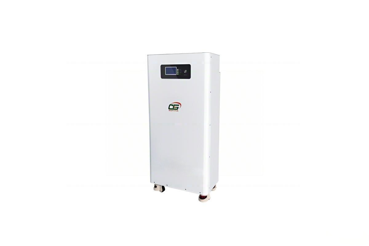
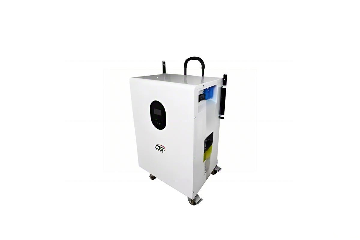
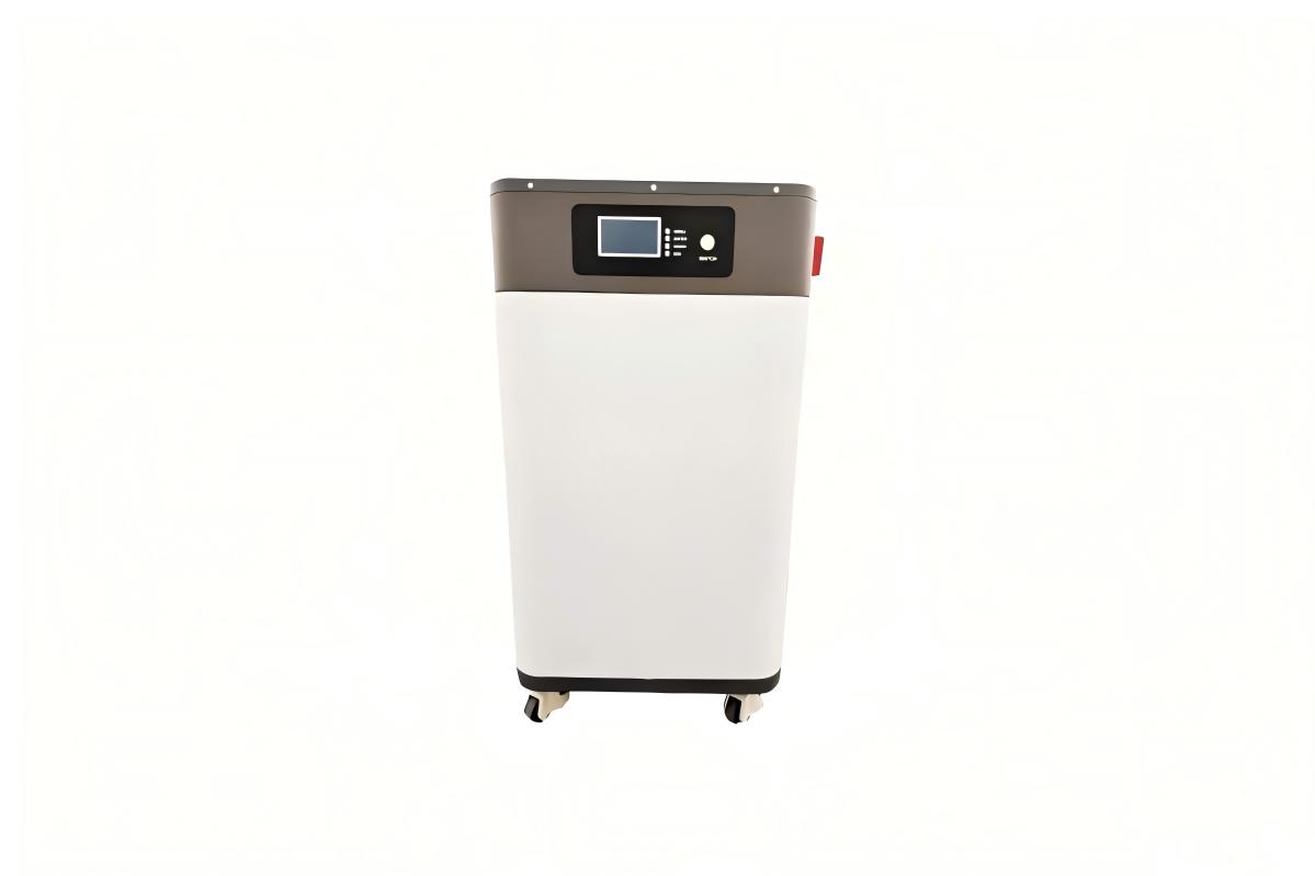
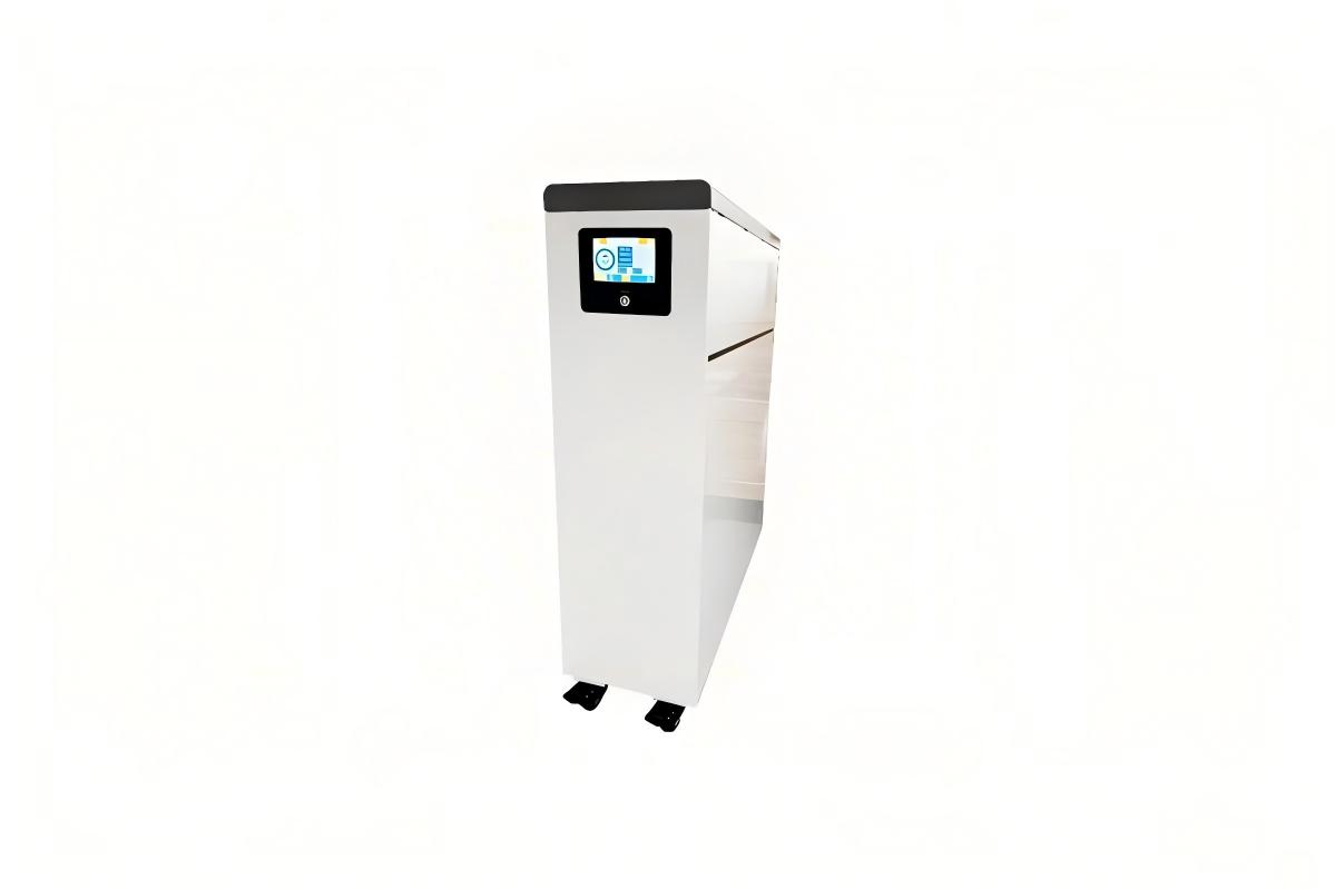
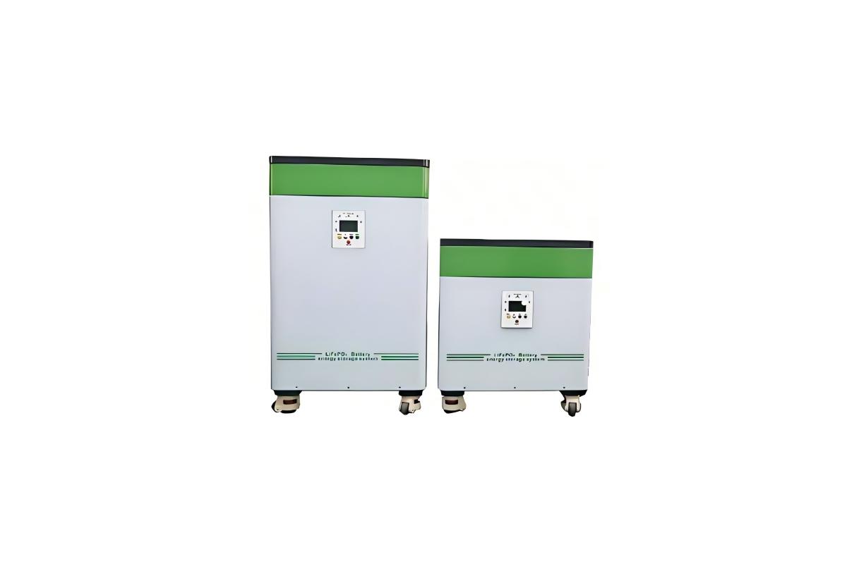
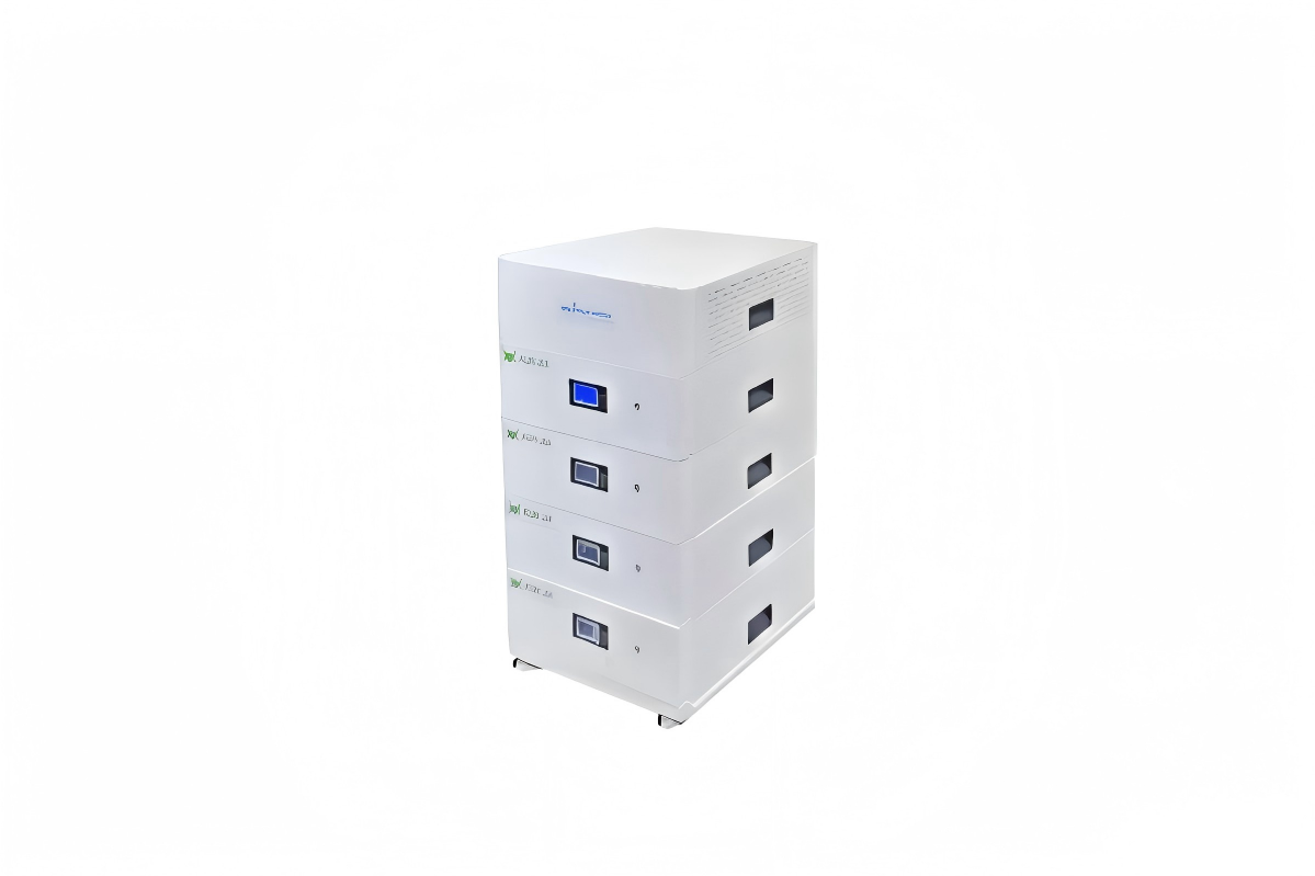
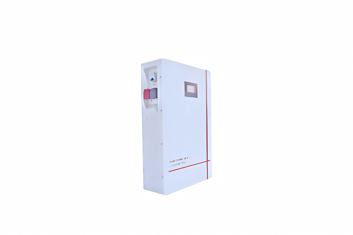
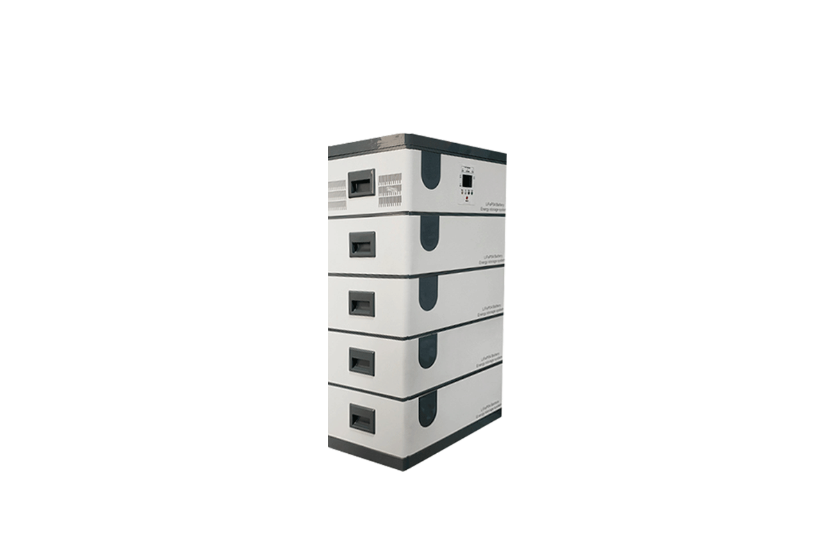
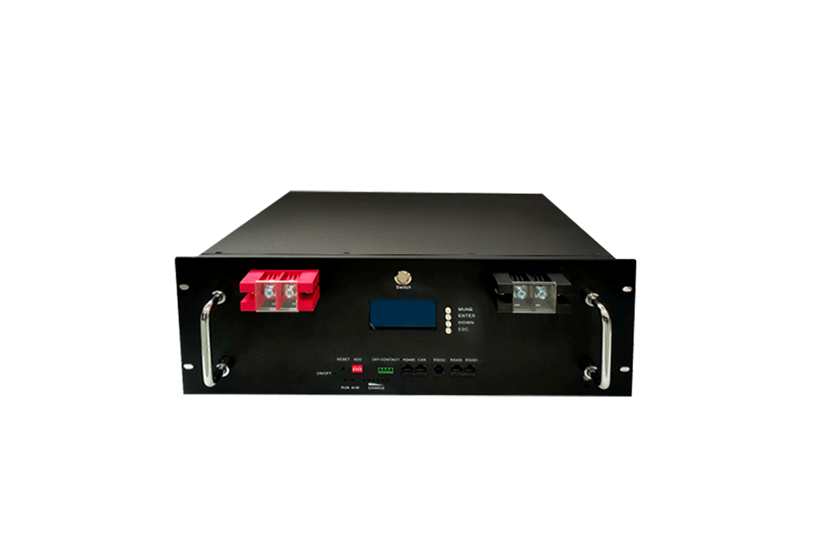
LiFePO₄ Battery Bank: Typically consists of 160 cells (3.2V/100Ah) configured into a 512V system. It serves as the energy storage core, achieving 20kW capacity through series-parallel connection (16 cells in series form 1 string of 51.2V, and 10 such strings connected in parallel).
Inverter: Choose a 25kW model with 512VDC input and 220VAC output, equipped with islanding protection. Its main function is to convert DC power from the battery bank to AC power that matches the grid’s frequency and voltage.
PV Combiner Box: Select a model with 10-string input and 100A rating. It merges the current from multiple PV strings and is internally equipped with surge protectors to shield the system from voltage spikes.
BMS (Battery Management System): Use a BMS compatible with LiFePO₄ batteries, which supports cell voltage balancing. It monitors the real-time status of each battery cell and prevents overcharging or over-discharging to protect the battery bank.
(2) Cable & Hardware
DC Cables: For battery interconnections, use 16mm² copper cables; for connections between the battery bank and inverter, use 20mm² copper cables. All DC cables must comply with T/DCB XXX-2024 standard, with a rated voltage of DC 1000V.
AC Cables: For grid connection, adopt THHN-type 4mm² cables. These cables are flame-retardant and heat-resistant, with a maximum operating temperature of 90℃.
Hardware: Prepare insulated terminals for secure cable connections, 2P 100A battery switches to control the DC circuit, and MC4 connectors for linking PV array components.
(3) Safety & Test Tools
Safety gear includes insulated gloves (with a rating of ≥1000V), safety glasses, and anti-static shoes to protect operators from electrical hazards.
Test tools cover a multimeter (with a DC voltage range of ≥1000V for measuring battery and circuit voltages), a thermal imager (for detecting abnormal heat in components), and a megohmmeter (for insulation resistance testing of cables and equipment).
II. Core Installation Procedures
1. Battery Bank Assembly
(1) Cabinet Fixation
Mount battery cabinets on a concrete foundation (with a load-bearing capacity of ≥500kg/m²) or anti-rust steel brackets. Use M12×100mm expansion bolts to firmly secure the cabinets to the ground, ensuring stability during operation.
(2) Battery Module Connection
Series-Parallel Configuration: To form a 512V system, connect 16 battery cells in series (each string reaches 51.2V) and then connect 10 such series strings in parallel (achieving a total capacity of 20kW·h). Use an insulated wrench to tighten the terminals, applying a torque of 8–10 N·m for copper terminals to ensure good contact without damaging the terminals.
Polarity Check: Strictly follow the polarity markings—connect red cables to positive (+) terminals and black cables to negative (-) terminals. Reversing the polarity may cause irreversible damage to the BMS.
Cable Management: Use cable ties to organize and secure interconnection cables, avoiding cable overlap. Overlapping cables can lead to heat accumulation, which affects the battery’s operating temperature and lifespan.
2. Combiner Box & Inverter Installation
(1) PV Combiner Box Setup
Install the combiner box within 5m of the PV array to minimize line loss. Each PV string (composed of 10×540W panels) is connected to the combiner box using 4mm² PV cables, with black cables for positive connections and red cables for negative connections.
Inside the combiner box, install 15A DC fuses for each PV string (to protect against overcurrent) and a DC 1000V-rated surge protector (to safeguard the system from lightning or grid voltage surges).
(2) Inverter Installation
Mount the inverter on a vertical wall, leaving a minimum 30cm gap between the inverter and the wall to facilitate heat dissipation. Ensure the AC output terminal is positioned away from water sources (e.g., faucets, downspouts) to prevent water damage.
Connect the combiner box to the inverter’s DC input using 20mm² cables, keeping the cable length ≤50m to minimize DC line loss and ensure efficient power transmission.
3. Wiring & Grounding
(1) DC Wiring (Battery → Inverter)
Use 16mm² stranded copper cables (which are flexible and suitable for carrying large currents). Strip 15mm of insulation from the cable ends and crimp insulated terminals onto the stripped ends to ensure secure connections.
Secure the cabled terminals to the inverter’s DC terminal block, applying a torque of 12 N·m. After connection, cover the terminals with insulation caps to prevent accidental contact and short circuits.
(2) AC Wiring (Inverter → Grid)
Use 4mm² THHN cables, following NEC color-coding standards: black or red cables for live wires, white cables for neutral wires, and green cables for ground wires.
Connect the inverter’s AC output to the grid’s distribution panel via a 2P 100A breaker. Before connection, confirm that the inverter’s AC output voltage (220V or 380V) matches the grid’s rated voltage to avoid compatibility issues.
(3) Grounding System
Install a grounding rod (with a length of ≥2.5m) at a location 3m away from the equipment to prevent interference. Use 10mm² green cables to connect the battery cabinet, inverter, and combiner box to the grounding rod, forming a unified grounding system.
Use a megohmmeter to test the grounding resistance, ensuring it is ≤4Ω. A resistance exceeding 4Ω may reduce the effectiveness of lightning protection and electrical fault grounding.
4. BMS Integration
Connect the BMS to the battery bank through a communication port (either RS485 or CAN bus). Configure key BMS parameters: set the overcharge voltage to 3.65V per cell, the over-discharge voltage to 2.5V per cell, and the temperature protection thresholds (shutdown when the temperature exceeds 50℃ or drops below 0℃).
Establish a communication link between the BMS and the inverter to enable real-time data synchronization, such as sharing SOC (State of Charge) levels and individual cell voltage data. This ensures coordinated operation of the battery bank and inverter.
III. Commissioning & Grid Connection
1. Pre-Startup Inspection
Visual Check: Conduct a comprehensive visual inspection—ensure all terminals are tightly connected, cables are routed correctly (without kinks or damage), and no tools or debris are left inside the equipment cabinets.
Insulation Test: Use a megohmmeter to test the insulation resistance of DC cables, requiring a minimum resistance of ≥10MΩ at 500V DC. Low insulation resistance indicates potential cable damage or moisture infiltration, which needs to be addressed before startup.
Battery Initialization: Before starting the system, charge the battery bank to 30% SOC using a 0.2C current (4A for a 20kW·h battery bank). This initial charge activates the battery cells and ensures stable performance during subsequent commissioning.
2. Phased Commissioning
(1) Single-Unit Testing
Battery Bank: Use a multimeter to measure the total voltage of the battery bank, which should be 512V±10V. Additionally, check the voltage of each individual cell—ensure the voltage deviation between cells is ≤0.1V. Significant deviations indicate cell imbalance and require adjustment.
Inverter: Activate the inverter in "off-grid mode" (disconnected from the grid) to test its AC output. The output frequency should be 50Hz±0.5Hz, and the voltage should match the rated AC output (220V or 380V), confirming the inverter’s basic functionality.
(2) Sub-System Testing
Charging Cycle: Connect the PV array to the system and monitor the charging process. Verify that the BMS controls the charging current to ≤0.5C (10A for a 20kW·h battery bank), preventing overcurrent charging that could damage the battery.
Discharging Cycle: Connect a 10kW load to the system and monitor the battery temperature during discharge. The temperature should remain ≤35℃; if it exceeds this threshold, check the cooling system and reduce the load if necessary.
(3) Full-System Commissioning
Switch the inverter to "grid-connected mode" and check the grid connection indicator on the inverter— a steady green light indicates normal grid connection. If the indicator flashes or turns red, troubleshoot grid compatibility (e.g., voltage/frequency mismatch).
Test the system’s protection functions: simulate a grid outage (by disconnecting the grid breaker) to verify the islanding protection. The inverter should shut down within 2s to comply with safety standards and avoid feeding power into a dead grid.
3. Grid Connection Approval
Compile commissioning reports, including insulation test results, BMS operation logs, and inverter performance data. Submit these reports to the local utility company for review.
Only after obtaining a grid-connection certificate from the utility company can the system be put into formal operation. Do not operate the system without official approval, as it may violate grid regulations.
IV. Safety & Post-Installation Notes
1. Operation Safety
Power-Off Sequence: When shutting down the system, follow the specified order: first turn off the PV array switch (to cut off input power), then turn off the battery bank DC switch, and finally turn off the inverter AC switch. Wait 5 minutes after power-off to allow residual power in the system to discharge before performing any maintenance.
Emergency Handling: If the battery temperature exceeds 40℃, or if abnormal odors (e.g., burnt plastic) are detected, immediately cut off all power sources. Use CO₂ or dry powder fire extinguishers to handle potential fires—never use water, as it conducts electricity and may exacerbate hazards.
2. Post-Installation Maintenance
Record initial operating parameters, such as individual cell voltages, insulation resistance values, and inverter efficiency. These baseline data serve as a reference for future maintenance and help identify performance degradation.
Inspect cable terminals monthly for signs of corrosion or looseness. If corrosion is found, clean the terminals with alcohol; if terminals are loose, retighten them to the specified torque.
Calibrate the BMS every 6 months to ensure accurate SOC calculation and cell voltage balancing. Outdated BMS calibration can lead to incorrect charge/discharge control and shorten battery life.
3. Compliance Reminders
All cables used in the system must meet the requirements of GB/T 12706.1, which specifies insulation standards for DC 1000V cables. Using non-compliant cables increases the risk of electrical leakage or short circuits.
Retain all installation records (e.g., permits, test reports, equipment manuals) for at least 5 years. These records may be required for utility company inspections or warranty claims.
V. Troubleshooting During Installation
1. Battery Voltage Imbalance Exceeding 0.2V
Possible causes include loose terminal connections or faulty battery cells. Troubleshooting steps: First, power off the system and use an insulated wrench to re-tighten all terminals, applying a torque of 8N·m (consistent with installation standards). Second, use a multimeter to measure the voltage of each cell—identify and replace cells with abnormal voltages (those deviating by more than 0.2V from the average cell voltage) to restore balance.
2. Inverter Fails to Start
Common causes are low battery SOC (State of Charge) or incorrect wiring polarity. Troubleshooting steps: First, check the battery SOC using the BMS or a multimeter—if it is below 30%, charge the battery bank to above 30% SOC using a compatible charger. Second, inspect the AC and DC wiring connections to the inverter, verifying that the polarity (positive/negative for DC, live/neutral for AC) matches the inverter’s markings. Correct any reversed connections before restarting.
3. Insulation Resistance Below 10MΩ
This issue is typically caused by damaged cables (e.g., cracked insulation) or moisture infiltration into equipment cabinets. Troubleshooting steps: First, visually inspect all DC and AC cables for signs of damage—replace any cables with cracked, frayed, or worn insulation. Second, check the internal environment of battery cabinets and the inverter—if moisture is present, use desiccant bags to absorb moisture and ensure proper ventilation to dry the cabinet. Re-test the insulation resistance after addressing these issues to confirm it meets the ≥10MΩ requirement.


 59911926@qq.com/sales@goldenfuturehk.com
 13316809242 / 15816897019
 Inquiry
 Home >