


Time:2025-10-22 Views:1
I. Preliminary Planning Stage: Accurately Matching Load and Environmental Requirements
1. Calculating Load and Energy Storage Requirements
Core Metrics: Determine energy storage capacity based on average daily electricity consumption × number of backup days, reserving 20% redundancy to handle peak loads.
▶ Example: If average daily electricity consumption is 60 kWh (e.g., a small factory/remote community), and a two-day backup design is used, 150 kWh of energy storage capacity is required (60 × 2 ÷ 0.8, with a depth of charge/discharge of 80%).
Key Operations:
① Count Load Types: For inductive loads (motors, air conditioners), reserve three times the starting power. For example, a 5 kW motor requires an inverter capable of 15 kW peak output.
② Collect Environmental Parameters: Record local average daily sunshine hours (e.g., approximately 4.5 hours in Shanghai) and extreme temperatures (-15°C to 50°C). Determine the module tilt angle (±5° at latitude) and the battery temperature rating. 2. System Power Ratio Design
Core Principle: PV module power should be slightly higher than the inverter's rated power (to compensate for losses), and the battery capacity should match the average daily power generation.
▶ Standard ratio: 20kW inverter + 22kW PV modules + 150kWh energy storage battery (average daily power generation of 60kWh, providing two days of backup).
Estimated Installation Area: Polycrystalline silicon modules require approximately 200㎡ (e.g., 80 250W modules), while monocrystalline silicon modules can be reduced to 180㎡ (with a 5% higher conversion efficiency).
II. Core Component Selection: Focus on Reliability and Compatibility
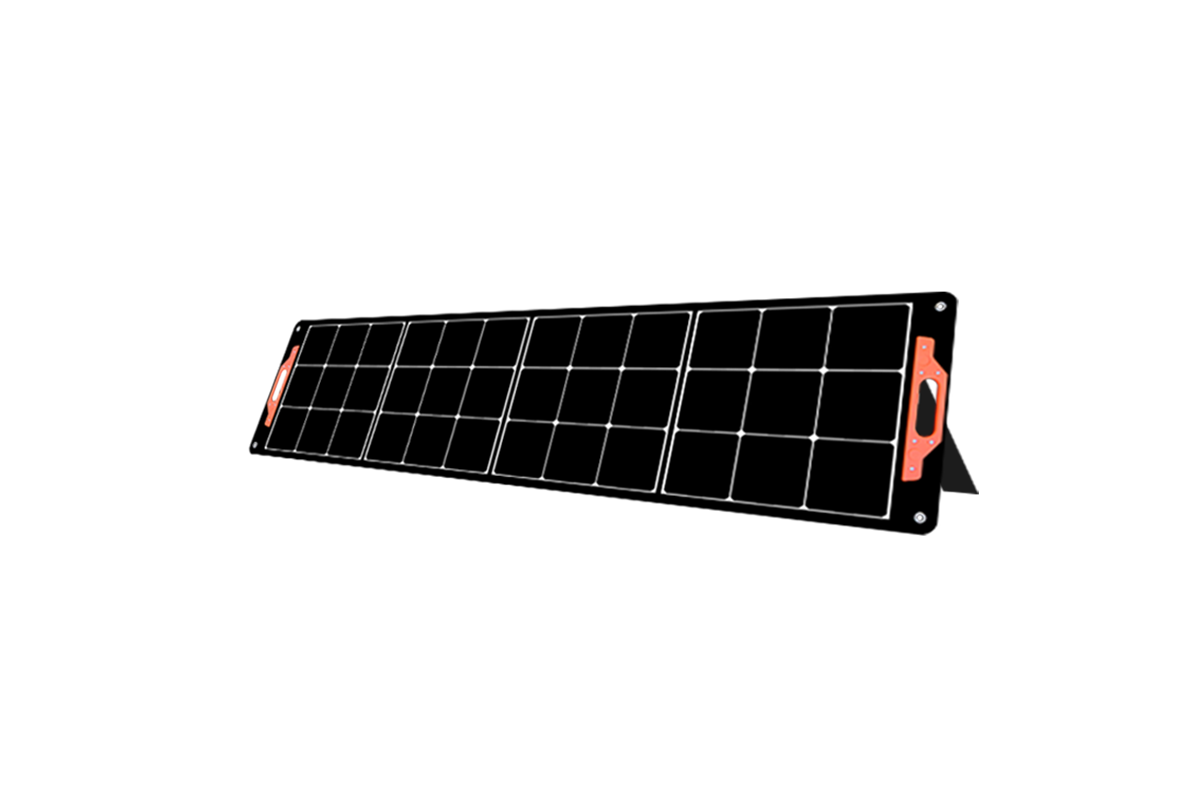
1. PV Modules: Prioritize Efficiency and Durability
Polycrystalline Silicon Modules:
Recommended Specifications: 250W per module, 80 modules in series;
Applicable Scenarios: General use, budget-constrained projects;
Key Advantages: High cost-effectiveness and excellent low-light response. Monocrystalline Silicon Modules:
Recommended Specifications: 550W/module, 40 modules in series;
Suitable Applications: High-insolation areas and space-constrained locations;
Key Advantages: Conversion efficiency ≥ 23%, long lifespan (25-year warranty).
Key Requirements: Wind load resistance ≥ 2400Pa, salt spray corrosion resistance (coastal/island locations), temperature coefficient ≤ -0.34%/°C.
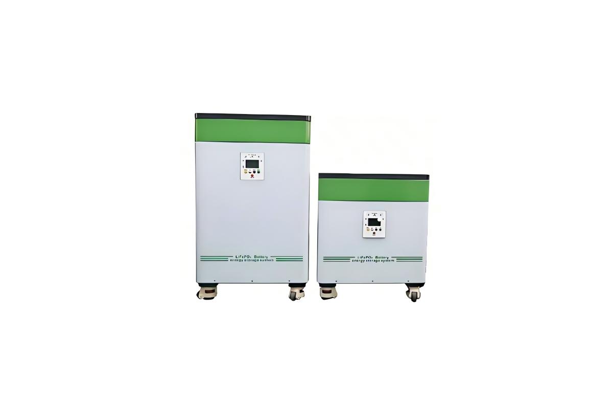
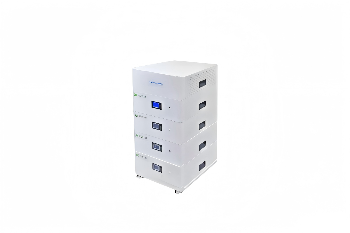
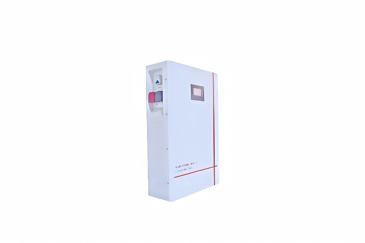
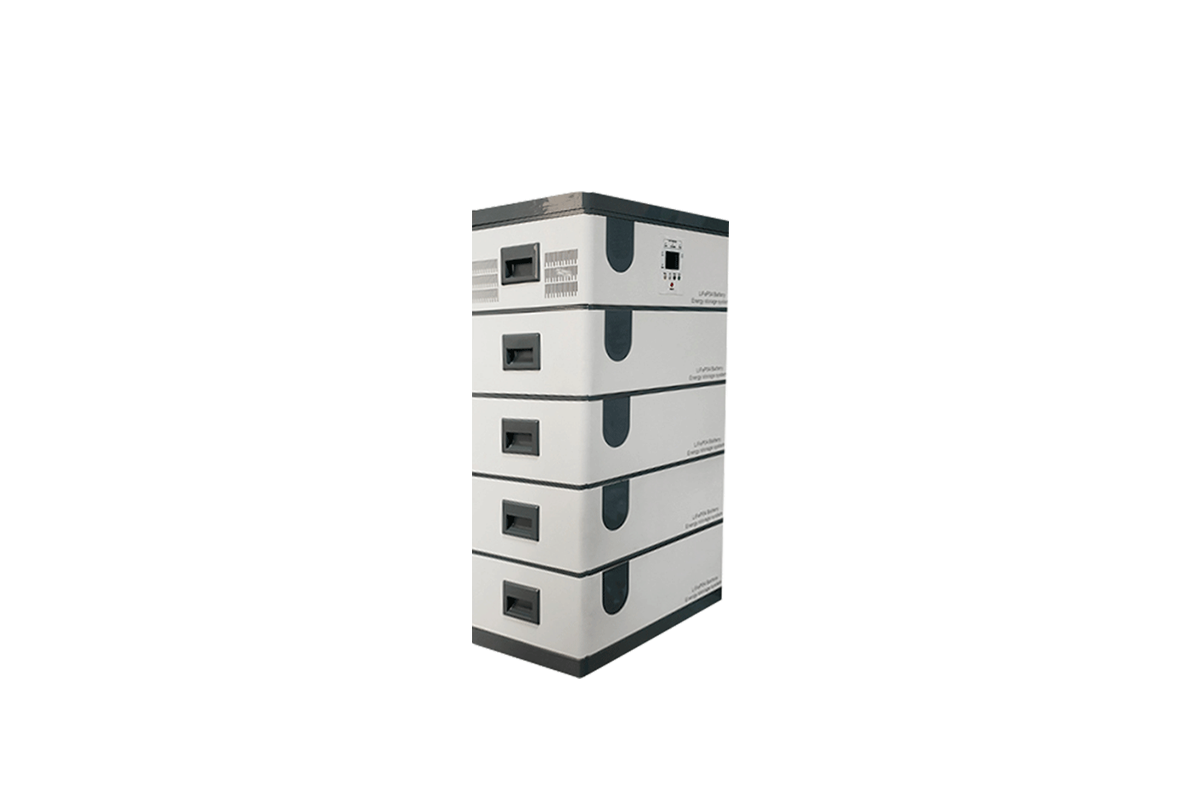
2. Energy Storage Battery: Safety and Cycle Life
Preferred Option: Lithium Iron Phosphate Battery (automotive-grade standard)
▶ Example Specification: 48V 3000Ah (144kWh), using a 14-series/3-parallel configuration (3.2V 15Ah cells);
▶ Key Advantages: Cycle life > 4000 cycles (10+ years of daily charge and discharge), high temperature resistance (-20°C to 60°C), and support for 1C fast charging. Alternative: Lead-acid Batteries
▶ Example Specifications: 2V 600Ah, 110 batteries in series (132kWh);
▶ Suitable for: Extremely low budget, ambient temperature environment (lifespan 2-3 years, requires regular water replenishment).
3. Off-grid Inverter: Stable Load Capacity is Key
Recommended Model: Power Frequency Isolation Inverter (20kW Class)
▶ Core Parameters:
Rated Power: 20kW, Peak Power: 40kW (supports motor starting);
DC Input: 192V/240V selectable, wide voltage range 172-340V;
Conversion Efficiency: >93%, no-load loss <1%;
Protection Functions: Overvoltage/overcurrent/short-circuit/overtemperature protection.
▶ Key Features: Built-in MPPT controller (tracking efficiency >99%), LCD display of operating parameters, and RS485 remote monitoring support. 4. Auxiliary Equipment Selection
MPPT Controller: If the inverter does not have an integrated one, select a 200A/192V model (tracking voltage range 100-800V);
Mounting System: Concrete posts (ground mounting) or color-coated steel tile clamps (roof mounting), galvanized for corrosion protection;
Cable: PV1-F 16mm² for DC (current carrying 50A), YJV 316mm² for AC (rated current 91A).
III. System Integration and Installation: Strict Control of Stability and Safety
1. PV Array Installation
Core Requirements: Tilt angle of 30° ± 5°, spacing ≥ 1.5 times the module length (to avoid obstruction), and four modules connected in series form one circuit (20 circuits total);
Key Operations:
① Use a laser level to calibrate the bracket flatness (deviation ≤ 2mm/m), and tighten the bolts to a torque of 25N·m;
② Install windbreak cables in coastal areas, and face the module junction boxes downward (to prevent rainwater infiltration).
2. Battery Pack Deployment
Core Requirements: Battery cabinet spacing ≥ 0.8m (for heat dissipation), ≥ 15cm above the ground (for moisture protection), and maintain an ambient temperature of 5-35°C;
Key Operations:
① Use copper busbars (current carrying capacity ≥ 500A) for series wiring, apply conductive paste to prevent oxidation, and tighten the bolts to a torque of 12N·m;
② Install a DC circuit breaker (300A) on the positive terminal of the battery pack, and connect the negative terminal to the lightning protection ground (ground resistance ≤ 4Ω). 3. Electrical System Connection
Core Specifications: Physically separate AC and DC circuits, with cables protected by galvanized pipe (buried at a depth of ≥ 0.7m).
Key Operations:
① Connect the inverter input to a DC combiner box (with 16A fuses per circuit) and the output to an AC distribution cabinet (including a 250A main switch).
② Grounding System: Connect the module rack, battery cabinet, and inverter housing to a common ground grid. Test the ground resistance with a megohmmeter to ensure compliance.
IV. Scenario Adaptation and Optimization: Targeted Solutions
1. Industrial/Commercial Scenarios (such as logistics warehouses and small factories)
Enhanced Configuration:
① Select an inverter with a 380V three-phase output (suitable for industrial motors) and install an AC bypass (automatic switchover in the event of a mains failure).
② Expand the battery pack capacity to 200kWh (with a 3-day backup capacity) and incorporate an air cooling system (starts when the ambient temperature exceeds 40°C).
Key Test: Load test with a 5kW motor, dynamic response ≤ 50ms, voltage fluctuation ≤ 5%. 2. Remote Areas (e.g., Mountainous Areas, Island Islands)
Enhanced Configuration:
① Select wind- and sand-resistant modules (anti-reflective coating on the surface), and battery cabinets with IP54 protection (for heavy rain);
② Add a 15kW diesel generator for emergency backup, linked to the inverter (automatically starts when battery SOC < 20%).
Key Test: Simulate a force 8 gale, ensuring no deformation of the module brackets and continuous system power supply.
3. Emergency Backup Scenario (e.g., Medical Facilities, Telecommunications Base Stations)
Enhanced Configuration:
① Batteries support 0.5C fast charging (full charge in 4 hours), inverter switchover time < 10ms (seamless power supply);
② Add a remote monitoring module (use mobile app to view SOC and power generation), and provide SMS alarms for faults.
Key Test: Uninterrupted load switching during power outages, and stable off-grid operation for 72 hours. V. Commissioning and Operation and Maintenance: Ensuring Long-Term Stable Operation
1. System Commissioning (within 72 hours of installation)
Performance Testing:
① Power Generation Efficiency: Measured daily average power generation ≥ 60 kWh (Shanghai area), MPPT tracking efficiency > 98%;
② Battery Performance: Capacity decay ≤ 2% after 3 charge/discharge cycles, cell voltage difference ≤ 0.05V;
③ Protection Function: Simulate short circuit/overload, immediately shut down the inverter, and ensure no component damage.
2. Full-Cycle Operation and Maintenance Plan
Daily (Weekly):
Core Tasks: Clean the module surface and check the cable connector temperature;
Key Standards: Modules are unobstructed, and connector temperature is < 60°C.
Periodic (Every 3 months):
Core Tasks: Calibrate MPPT parameters and replenish battery balancing power;
Key Standards: Tracking voltage deviation ≤ 1V, cell voltage balance.
Annual:
Core Tasks: Check module power degradation and inverter insulation;
Key Standards: Power degradation ≤ 3%/year, insulation resistance > 100 MΩ. Warranty continuity: 10-year warranty for modules, 3-year warranty for inverters, and 5-year warranty for batteries (cycle count > 2,000 times).


 59911926@qq.com/sales@goldenfuturehk.com
 13316809242 / 15816897019
 Inquiry
 Home >